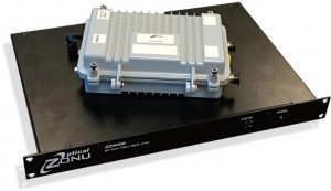
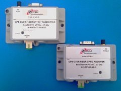
Optical Zonu GPS reference timing signals are widely used to synchronize communications for modern networking equipment like cellular base stations, allowing them to use limited bandwidth more efficiently and coordinate smooth handoffs. The recent proliferation of small cells for cellular service, utilization of CRAN centers, and technology updates have increased the demand for GPS timing distribution, but this has not come without complication.
GPS systems typically consist of an active rooftop antenna, a GPS receiver and a length of coaxial cable to connect them. A challenge arises, however, when the distance between the rooftop antenna and the cellular base station equipment (usually in the basement) is greater than 300 ft. Coaxial cable runs of over 300 ft are not practical for most GPS receiver systems, so a fiber optic link is required at these or greater distances, and Optical Zonu’s fiber optic links are some of the most trusted and cost-effective links in the industry.
The Base Unit RF outputs connect to your GPS receivers or base station equipment. The Base Unit is available with up to 1 to 16 RF outputs for point-to-point or point-to-multipoint connections. In addition, the fiber optic cable can be split up to 8 ways (16 splits are available for special order). The combination of optical and RF splitting permits easy routing of the GPS over thin optical fiber while providing the lowest cost per connection. This makes the solution ideal for C-RAN hubs and base station hotels. The Base Units are simply distributed in the racks with the BBUs or eNodeBs so the final connections require only lightweight, short RF jumpers. The transport is NEBS Level 3 certified permitting installation in Central Office environments and can be conveniently rack mounted.


